Railway Signaling Relay Selection: Critical Differences Between Vital and Industrial Safety Relays
Gravity Never Fails: The Physical Foundations of SIL 4 Relay Technology
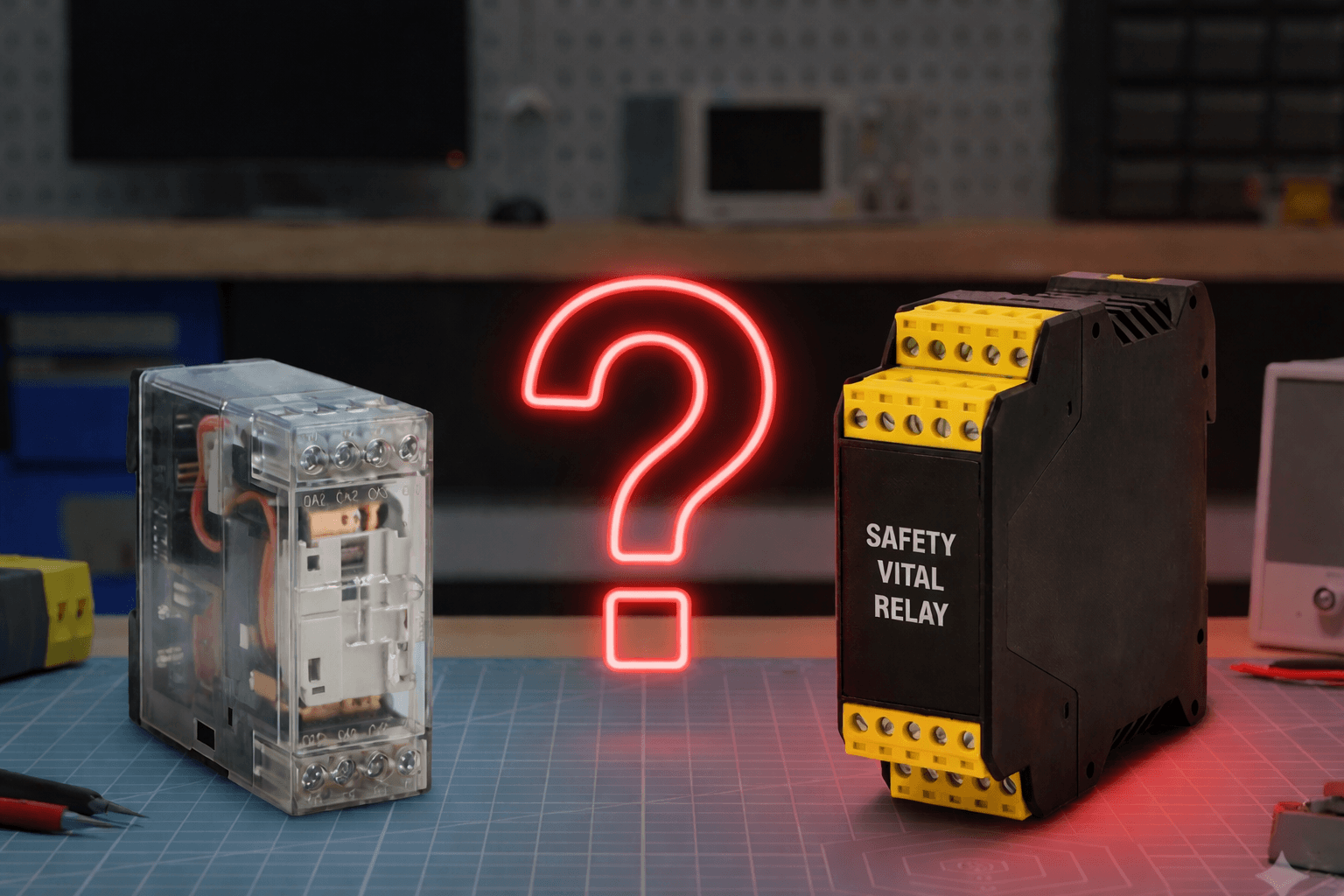
Can high-security industrial relays be used in interlocking systems? Or are only component-level certified SIL 4 relays permitted? This question points to a widespread conceptual confusion in the sector. The answer is not simply yes or no: Utilization is subject to specific architectural conditions.
Theoretical Background
The Two Worlds of Safety Relays
The selection of relays in railway safety depends on the design philosophy and certification approach. There are two primary categories:
|
Category |
Principle |
Examples |
Standalone SIL 4 |
|---|---|---|---|
|
Vital Relays |
Gravity + Carbon Contact |
Mors Smitt N.S1, Clearsy RS4 |
✅ Yes |
|
Industrial Safety Relays |
Forcibly Guided (EN 61810-3) |
Finder 7S, Dold OA, Arteche FF |
❌ No (Can be part of a system) |
Vital Relays
These relays represent the gold standard of railway signaling, rooted in a century of engineering heritage.
Gravity Fail-Safe (e.g., Mors Smitt N.S1):
- When the coil energy is removed, the opening of the contacts is entrusted not to a friction-prone spring force, but directly to gravity.
- A spring can fatigue or snap, but gravity never disappears.
- Therefore, these relays must always be mounted in a specific vertical orientation defined by their design parameters.
Carbon-Silver Contact Technology (e.g., Clearsy RS4):
- One of the contact tips is made of silver, and the mating tip is made of a carbon (graphite) alloy.
- By its metallurgical nature, carbon does not weld to silver; this physically prevents the contacts from fusing.
- Contact welding is rendered physically near-impossible.
Industrial Safety Relays: Forcibly Guided Contacts
Manufactured according to the EN 61810-3 (formerly EN 50205) standard, these relays pursue an entirely different safety strategy. Companies like Dold, Finder, and Arteche have established industry-standard products in this class.
Mechanical Linkage Principle:
- Normally Open (NO) and Normally Closed (NC) contacts are mechanically interlocked via a guiding rod (comb).
- If an NO contact welds due to excessive current or a short circuit, the mechanical rod physically prevents the NC contact from closing and the system from transitioning to an unsafe state.
- As mandated by the standard, a minimum functional gap of 0.5 mm is guaranteed between contacts.
The Critical Difference:
These relays do not prevent the metallurgical occurrence of welding; they merely report the condition to the controller once it happens.
Research Details: Root Cause Analysis
Field Scenario: Relay Selection in Interlocking Panels
An EPC (Engineering, Procurement, and Construction) contractor is selecting relays for an electronic interlocking project. There are two options on the table:
|
Option |
Product |
Unit Cost |
Requirement |
|---|---|---|---|
|
A |
Clearsy RS4 (Vital) |
~€500 |
Standalone SIL 4, no feedback wiring needed |
|
B |
Finder 7S (Industrial) |
~€50 |
Requires PLC monitoring + redundant architecture |
Cost Discrepancy: The per-unit cost difference in the field is approximately tenfold. The Critical Question: Can Option B be utilized in the design?
Why Aren’t Industrial Relays SIL 4 Standalone?
|
Parameter |
Vital Relay |
Industrial Relay |
|---|---|---|
|
Weld Prevention |
Hardware / Physical Mechanism |
None (Relies on spring return) |
|
Fault Detection |
Inherently Independent |
External Control (PLC readback) |
|
Mounting Orientation |
strictly vertical (Gravity constraint) |
Omnidirectional |
|
Diagnostic Coverage |
Embedded within the design |
Dependent on system architecture and the PLC |
Deduction: Industrial safety relays do not possess a SIL rating on their own. However, within a redundant architecture boasting a 99% diagnostic coverage rate (employing 1oo2 redundancy alongside the readback process), they can be utilized as an integral component of a CENELEC SIL 4 compliant system.
Architectural Solution and Operational Logic
There are two distinct safety architectures in the market. One is predicated on purchasing safety, while the other revolves around constructing it holistically.
Approach A: Component-Level Architecture
Representative: Clearsy RS4 Series
This approach positions the product itself as a certified black box. The relay is a sealed unit designed according to SIL 4 requirements during the hardware design and manufacturing phases, possessing internal redundancy and inherent fail-safe capabilities.
- Operational Principle: The integrator drives the relay using standard industrial relay logic. The product’s safety case documentation is securely provided directly by the manufacturer.
- Wiring: Only the driving coil and transmission contact terminals are connected. It does absolutely not require an external control cable or specialized monitoring software on the safety PLC side.
- Internal Mechanism: The configuration of the mechanism and gravity within the relay inherently eliminates the risk of contact welding.
Commercial Equation:
- ✅ Plug-and-Play: The engineering burden and Independent Safety Assessor (ISA) approval process for the integrator are radically minimized.
- ❌ Cost: The standalone unit cost is exceedingly high (~€500).
- ❌ Supply Chain: Creates total dependency on a single or highly restricted supplier base (Monopoly).
Approach B: System-Level Architecture
Representatives: Arteche, Finder, Dold (Forcibly Guided Relays)
This approach aims to achieve the firm SIL 4 target by combining standard safety relays through an intelligent system architecture. Safety is not strictly embedded in the off-the-shelf product; it is meticulously concealed within the entirety of the designed circuit.
- Operational Principle: Instead of using a single relay, at least two relays with forcibly guided contacts are utilized, electrically wired in series (1oo2 Architecture).
- Wiring and Monitoring:
- Series Safety: The NO contacts of the dual relay set are wired in series to the field load. Even if one relay effectively welds, the other interrupts the circuit, mitigating the fault efficiently.
- Readback Process: The closed (NC) contacts of the relays are carefully wired to the digital input (DI) card of the safety PLC, enabling instantaneous monitoring of the relays’ mechanical states.
- Audit Logic: The safety PLC strictly verifies the state of the NC contacts before dispatching a drive command to the field. If a contact appears open while no energy is supplied to the field (indicating a welding syndrome), the system categorically refuses the drive command and locks into a safe state.
Commercial Equation:
- ✅ Cost-Effective: Up to 90% CAPEX savings in projects are achieved due to fundamentally low unit costs.
- ✅ Flexibility: Any EN 61810-3 (EN 50205) compliant standard product can be utilized.
- ❌ Engineering Burden: Circuit design, wiring complexity, and the ultimate safety proof responsibilities of the final system lie squarely on the shoulders of the integrator architect.
Conclusion
Decision Matrix
|
Project Scenario |
Recommended Architecture |
Rationale |
|---|---|---|
|
Low-volume project, tight schedule |
Vital Relay (e.g., Clearsy RS4) |
To minimize engineering effort and ISA certification duration |
|
High-volume mainline project |
Industrial Relay + 1oo2 Architecture |
To optimize the Total Cost of Ownership (TCO) of the system |
|
Legacy system renovation |
Vital Relay |
To replace older generation relays 1-to-1 without structural modification |
|
New design, PLC-based interlocking |
Industrial Relay + Readback Loop |
To leverage the diagnostic capabilities the PLC already inherently possesses |
Summary Deductions:
- The concept of a “SIL 4 Relay” does not equate to a “SIL 4 System”: A single component may possess a SIL 4 hardware label, but system engineering is a comprehensive, holistic endeavor.
- Gravity vs. Spring Force: The safety of vital relays relies heavily on immutable physical laws of nature, whereas industrial safety relays necessitate external diagnostic intelligence to effectively detect latent flaws.
- Cost vs. Responsibility Trade-off: Choosing inexpensive components decisively incurs a high engineering burden and continuous ISA auditing, whereas expensive components systematically yield a comfortable, stress-free integration. The supply chain strategy is directly proportional to a firm’s internal engineering confidence.
References
- EN 61810-3: Electromechanical elementary relays – Relays with forcibly guided contacts
- EN 50129: Railway applications – Communication, signalling and processing systems
- Mors Smitt N.S1 Technical Documentation
- Clearsy RS4 Functional Safety Guidelines
- HIMA SILworX Application Notes
📋 Related Links
🔗 Related Article: → Strategic Analysis: CENELEC SIL 4 Relay Procurement Strategies and Market Dynamics in Railway Signaling
Last update: March 2026 | Version: 1.1